June 2008
I am building this pedal for my new JTM45 rig. I am basically taking the General Guitar Gadgets ITS8 Tube Screamer clone I built and putting it into an enclosure with the General Guitar Gadgets MXR Microamp clone that I also built. The pedal was originally called the DriBoo (DRY-boo) for Drive and Boost put together, but I changed it to MicroScream. I really like the sound of the Tube Screamer followed by the Microamp. It allows you to have a good crunchy sound and then boost it when you do a lead. You can also run the pedal into a clean amp and use only the boost for louder clean sound. I almost went with a Fulltone Full-drive 2 until I realized that the boost really isn't a boost and it must be used when the overdrive is engaged.
Here goes:
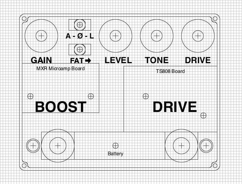
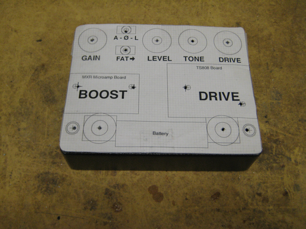
Ok, first the design. I use this really killer program for the Mac called Concept Draw. I used the dimensions of a 1590NS enclosure that I got from Pedal Parts Plus and went to work. It is going to be a tight squeeze but with a CAD program you can really see where the parts are going to go. Here is an image of the final design. It took a long time to finally get the knobs where I wanted them.
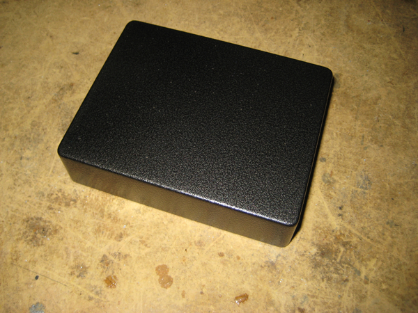
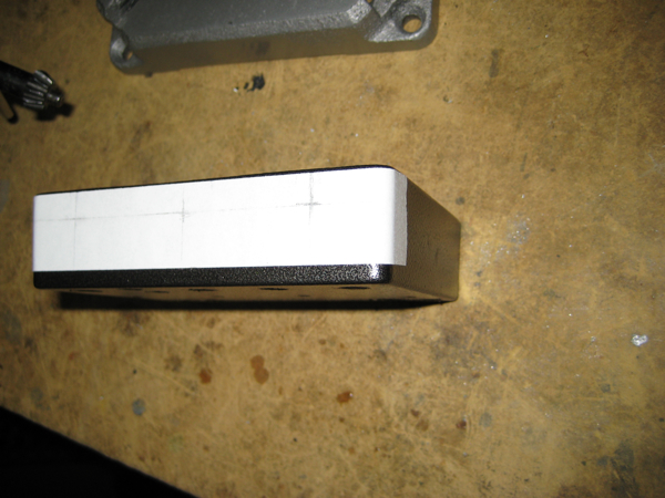
The parts started showing up. The enclosure I got from Pedal Parts
Plus but was way darker than the picture on their web site. I was
going to do a waterslide decal for the text as read about on the BYOC
forum, but it will only work on a light color. I will use this box
as the prototype. Connie at PPP is great and is sending me two metallic
silver boxes which I will transfer this build over to when they arrive.
It actually worked out good because I can work on the finish of the
final box and get to play the pedal in this box.
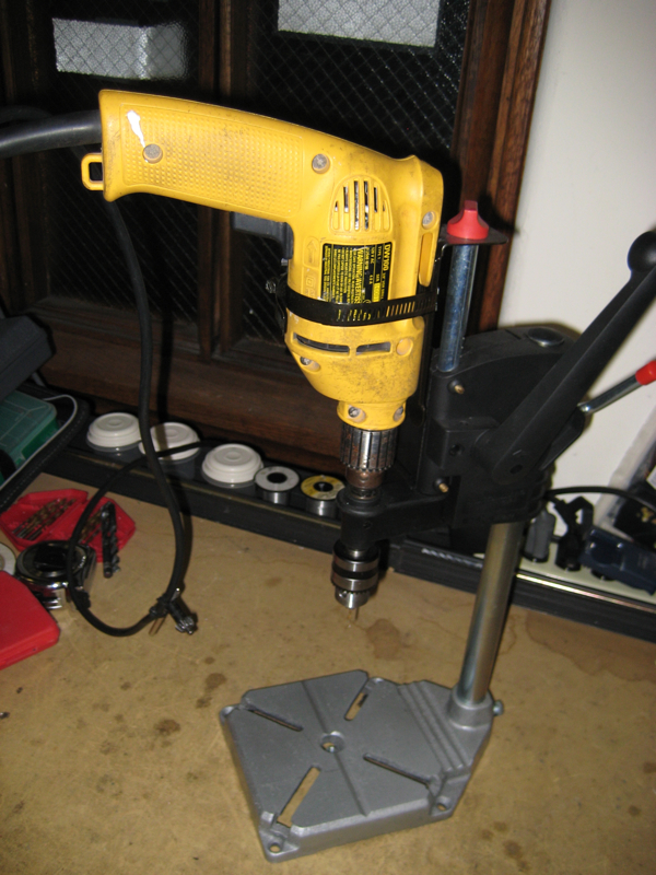
I set up my Wolfcraft Drill press on my bench at work and got
ready to spray metal shavings all over my workbench and clothes.
*Note Always wear eye protection, ear protection, and gloves or you risk becoming a blind, deaf, one-handed guitar player thus leaving you with only one musical option - playing blues.
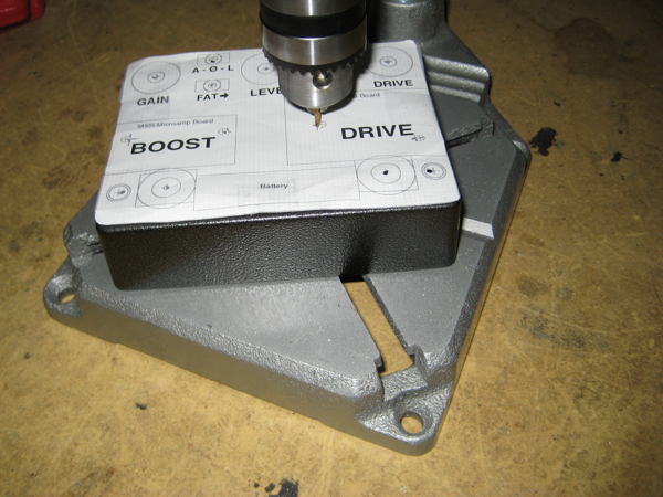
I taped my Concept Draw template onto the enclosure and drilled pilot
holes first. This makes for very accurate holes. I hate inaccurate holes
because I am a meticulous freak!
Here are all of the pilot holes drilled. I made a few minor adjustments
which I corrected on the layout for future use - looking good...
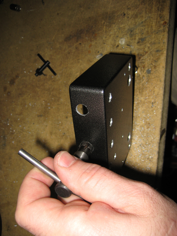
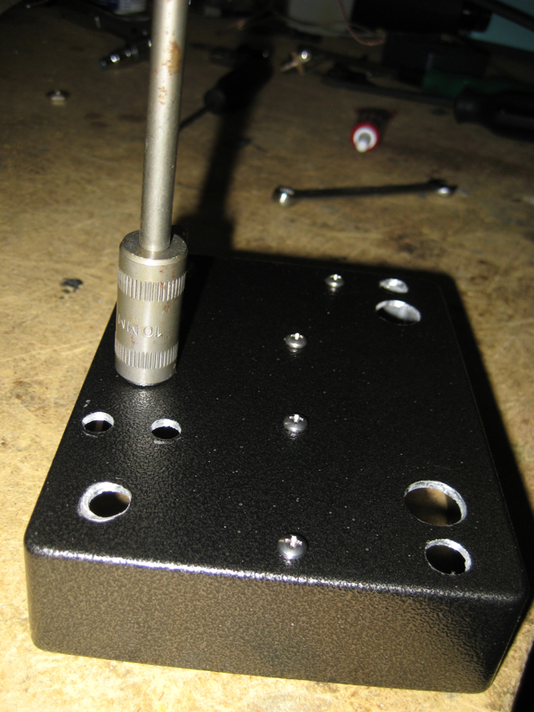
I used a bigger bit to widen some of the holes but I like to use a
tapered reamer to get a very exact fit for the controls. Man this is
turning into one big innuendo!

I next marked the edge holes for the 1/4" jacks and the AC Adapter jack.
Remember: Tape is your friend. It keeps the box from getting nicked up.
Drilled the edge holes and got back with the reamer to expand the holes
to the proper size. Ok, get your minds out of the gutter...
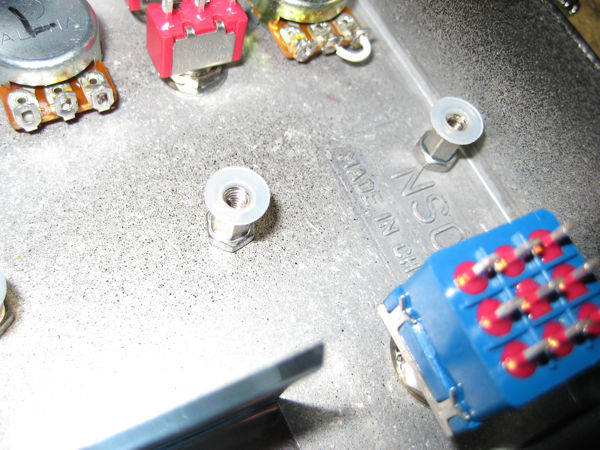
One of my biggest pet peeves is when people build these wonderful pedals
and then they use stick on plastic stand offs for the circuit board.
That is like putting those spinning hubcaps on a Bugatti
Veyron 16.4! For god sakes get some stainless steel under that
circuit board. I start with a 3/4" 4-40 stainless steel machine screw
and nut.
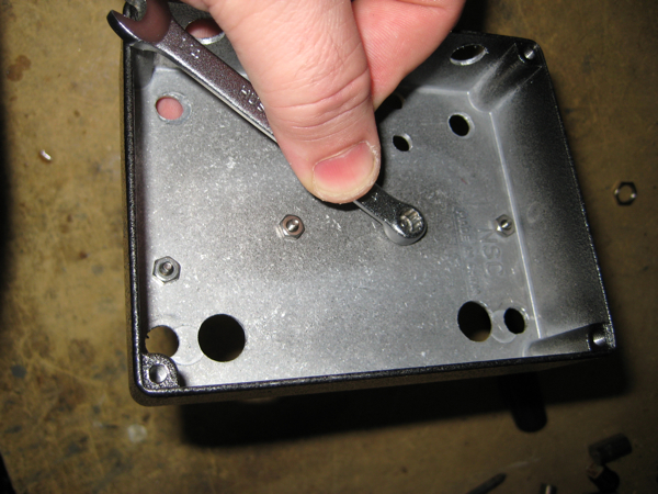
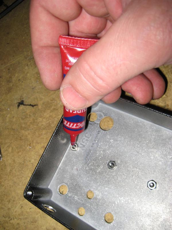
I also use Loctite thread locker to keep
any of these parts from vibrating lose. You never know when a natural
disaster will ravage your precious pedal into a heap of loosened nuts
and bolts.
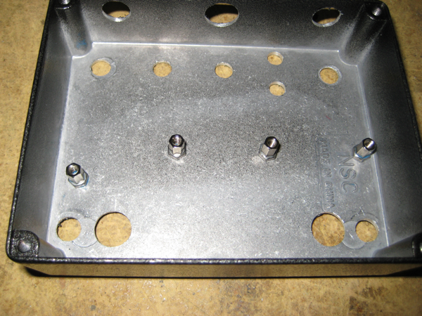
Then I add a 4-40 1/4" standoff. Is this over kill? Yes. Is it heavy
duty and cool and will last for ever. Yes. Do I carry things too far?
Yes... Life advice: NO PLIERS! Get a socket set and tighten those
standoffs down. You owe it to yourself to have good tools. Your good
enough and dang it, you deserve it. Not too tight or they will snap off.
Here are the stand-offs installed. So purty!
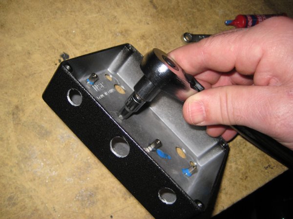
Next I started bolting in the components. Get yourself a set of nut
drivers too. it makes potentiometer installation a breeze. Or live with
the scratches from your channel locks a telltale badge of the uninformed
and ill equipped. Ignore the incongruence of the first pot hole. The
washer will cover it - yea, that's the ticket...
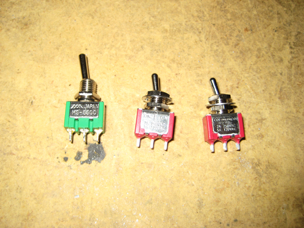
When I put the ITS8 together the first time it came with longer lever
switches. I felt these could easily be broken off since the pedal spends
most of it's time bouncing around in my messenger bag. A mouser catalog
and 2 hours of research I came up with shorter lever switches with good
specs.
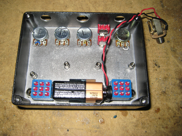
Here are most of the components bolted in. Another pet peeve of mine is
when batteries rattle around inside of pedal enclosures. Nothing says "I
don't care about leaking battery acid all over my pedal guts" like the
thump of a loose battery. I installed a narrow battery clip and bolted
it with a screw from an Apple G4 hard drive and a Nylok
nut on the outside.
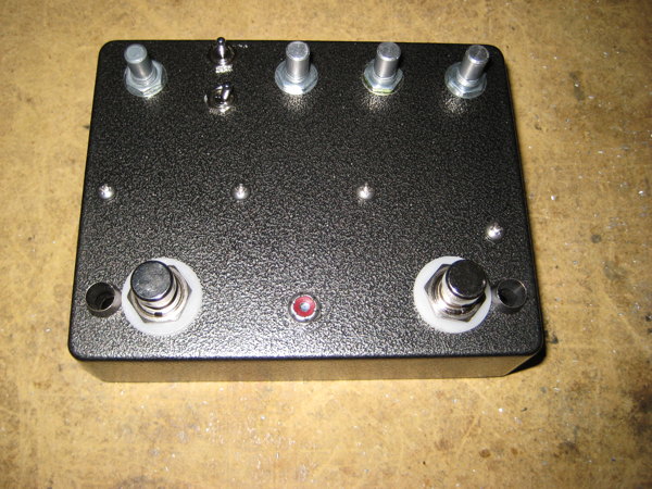
Here's the top with some of the parts in.
This is a test to see if the battery actually fits. Scale drawing
genius!
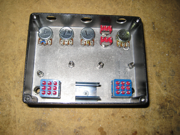
I didn't want the stand offs shorting anything out, so I utilized nylon
washers. I lightly super glued them to the stand offs so I could bolt
the circuit boards down.
I bolted the circuit boards in and used another couple of nylon washers
on top. It is super strong. I made use of many colors of wire deviating
from the GGG layouts. I always use yellow for output and pots get red,
white, and blue for wires 1,2, and 3.
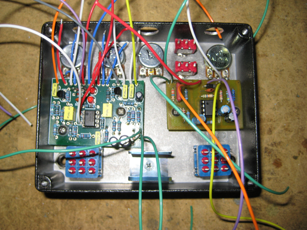
I soldered leads onto the LEDs to make them easier to work with. I will
be using resistors to "tune" the brightness of the LEDs used. I swear I
have a guitar body shape etched on the back of my retina from those
piercing blue ones!

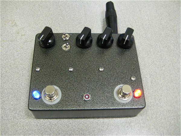
Here is the completed pedal gut shot. It took a long time but it came
out super. I will build you one but you are not going to like the price!
Here it is with LEDs off...
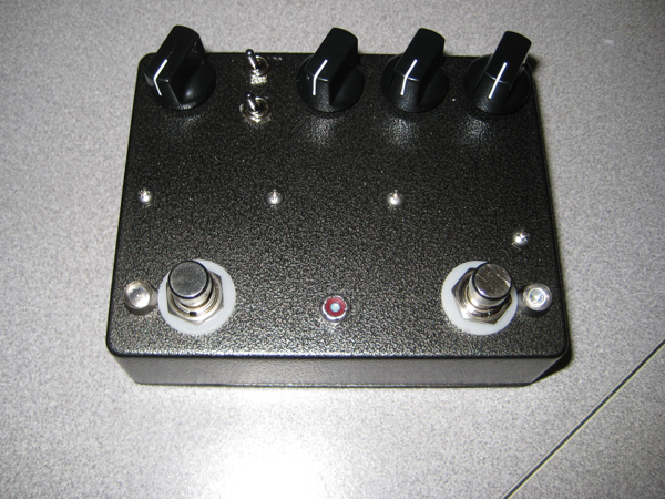
And LEDs on...
It sounds really amazing and does exactly what I want it to do. Now I
just have to sell my JCM800 2204 and build a JTM45 and I'll be set for
life! Come on, who am I kidding...
July 2008
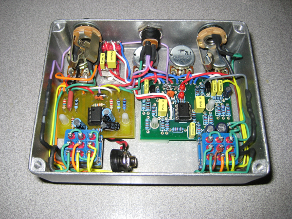
After using this pedal for a while I realized that I wanted the boost
switch on the outside. I also needed the boost pedal to be on the outside
just for ergonomics sake. This was tough to do because I still wanted
the signal routing to be the Tube Screamer first and the Microamp
second. This took a very long time but I got it done. Still very neat wiring.
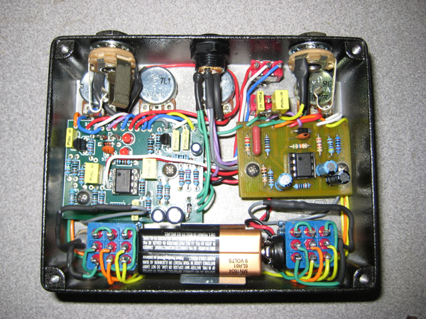
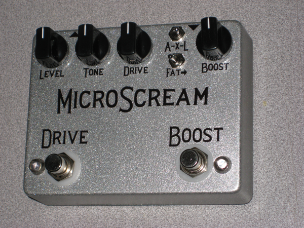
I also wanted the pedal to look more professional so I switched the standoffs
and added a waterslide decal. I also switched to a silver box and clear
coated it many times. A big thanks to mantas68 over at the
BYOC
forums
for helping me to learn how to do the waterslide decal!
Here's a gut shot:
August 2008
I sold my JCM800 2204 Rachelle amp and it kind of broke my heart, but I
got started on the Rachelle JTM45. I am using the blogger site instead of my own clunky blogging techniques in html. Click here
to check it out!
As much as I love this pedal I have decided that I need more gain than the Microamp side can provide. I am going to sell this one and then build a new dual Tube Screamer. I may just build 2 separate tube screamers for flexibility.
Clips soon!
This pedal was made into conjoined twins from these 2 builds. Click the
links to find out more details on the mods and guts.
General Guitar Gadgets MXR Microamp Clone
General Guitar Gadgets ITS8 Ibanez Tube Screamer TS808
Clone with Landgraff mods
Amp Builds:
Rachelle JTM45 - Currently in production
Rachelle Prototype - SOLD
Rachelle -
My one-of-a-kind personal amp - SOLD
Buy a
Rachelle amp! - SOLD
Check out my current band:
The Hornrims
If you live in the Tampa area, go
see my new rock musical in 2009!
Pericles
Buy some of my music on iTunes!
Support my kids dance lessons!
- The
Hornrims
- Joe Popp
- dogs on ice
Contact: Click here to
email Joe Popp
Visit: Joe Popp.net for other crazy stuff!
Visitors